Lithium Battery Protection for Small Projects
Lithium cells haven’t become the predominant power source for mobile electronics without reason. Circuits for their—very necessary—protection are naturally plentiful as well.
One particular weak point of many protection schemes, however, is deep discharge protection. Common practice is to discharge LiPo/LiIon cells no further than 3 V to not risk permanent damage. Yet, most protection ICs cut off only at 2.5 V, and you thus have to rely on additional battery voltage monitoring.
For many applications that is more than reasonable, since letting your microcontroller supervise the battery voltage can be used for useful state of charge information or even just an advance warning before shutdown. However, 3.7 V are a convenient voltage, not just for supplying a microcontroller, and even in that case, using an ADC or comparator pin just for battery voltage monitoring is overkill for simple projects which could be allowed to just switch off once their battery goes out.

Specifically looking for battery protection ICs with a higher cut-off voltage, I found the XB5358D0 with a threshold of 2.9 V. Not quite 3 V, but a lot better than the usual standard. The XB5358D0 also already includes its power MOSFETs, making the default application circuit incredibly simple.
With basically everything built in, this IC seemed like a good candidate for small battery-powered projects which don’t need a lot of power, letting me worry about other things than monitoring the battery voltage.
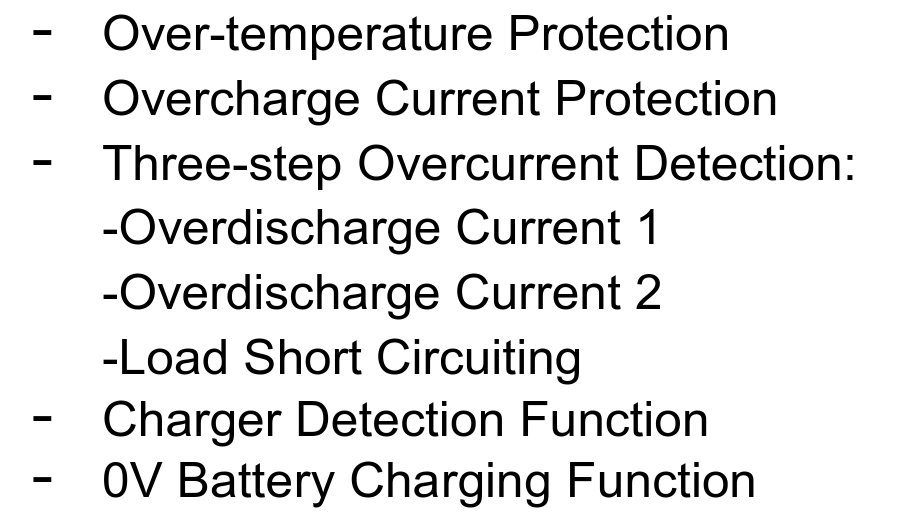
Protection against battery reversal
One thing the list of protection does not include is battery polarity reversal. And indeed, a quick test reveals that not only does it conduct between VM and VDD when inverted (which would not be catastrophic with the 100 Ω resistor limiting the current) but it does also switch the internal MOSFETs on, connecting VM and GND and relaying the wrong-polarity voltage to the connected circuit, without any overcurrent protection.
When the XB5358D0 is soldered directly to the battery, this isn’t an issue. But I also wanted to use it on PCBs with an 18650 battery holder, where it would be easy to insert the battery the wrong way. Luckily, a single MOSFET is enough to disconnect an inverted battery from the system ground.

The extra polarity check circuit also gives me the opportunity to add an LED that says ‘you put in the battery the wrong way, dingus!’ brightly.
Battery charging and full power path circuit
A charger can be connected directly to VBAT and GND, as both the XB5358 and MOSFET reversal protection work in both current directions. To switch over power sources for the supplied circuit when a charger is connected, the simplest solution would be a diode or combining VBAT and a charger input voltage VEXT.
Here, I’ve used another MOSFET (an AO3401A in my case, but again, pretty uncritical choice) to save on the forward voltage drop on VBAT.

The only thing out of the ordinary here are D2 and D3. These aren’t strictly necessary, but they make the switchover smoother: if omitted, connecting Q2’s gate straight to VEXT, Q2 can switch off before VEXT has reached a level higher than VDD. If VEXT falls and rises slowly, this can result in dips in VDD around a few hundred millivolts, depending on Q2’s gate threshold voltage.

With a single diode, the dips are still visible, but less severe. With two diodes, the switchover is entirely clean. If these diodes are necessary (the maximum drop is limited by the forward voltage of Q2’s body diode after all) depends on the supplied circuit, but the diagram above shows the circuit’s most generic form.
Resources
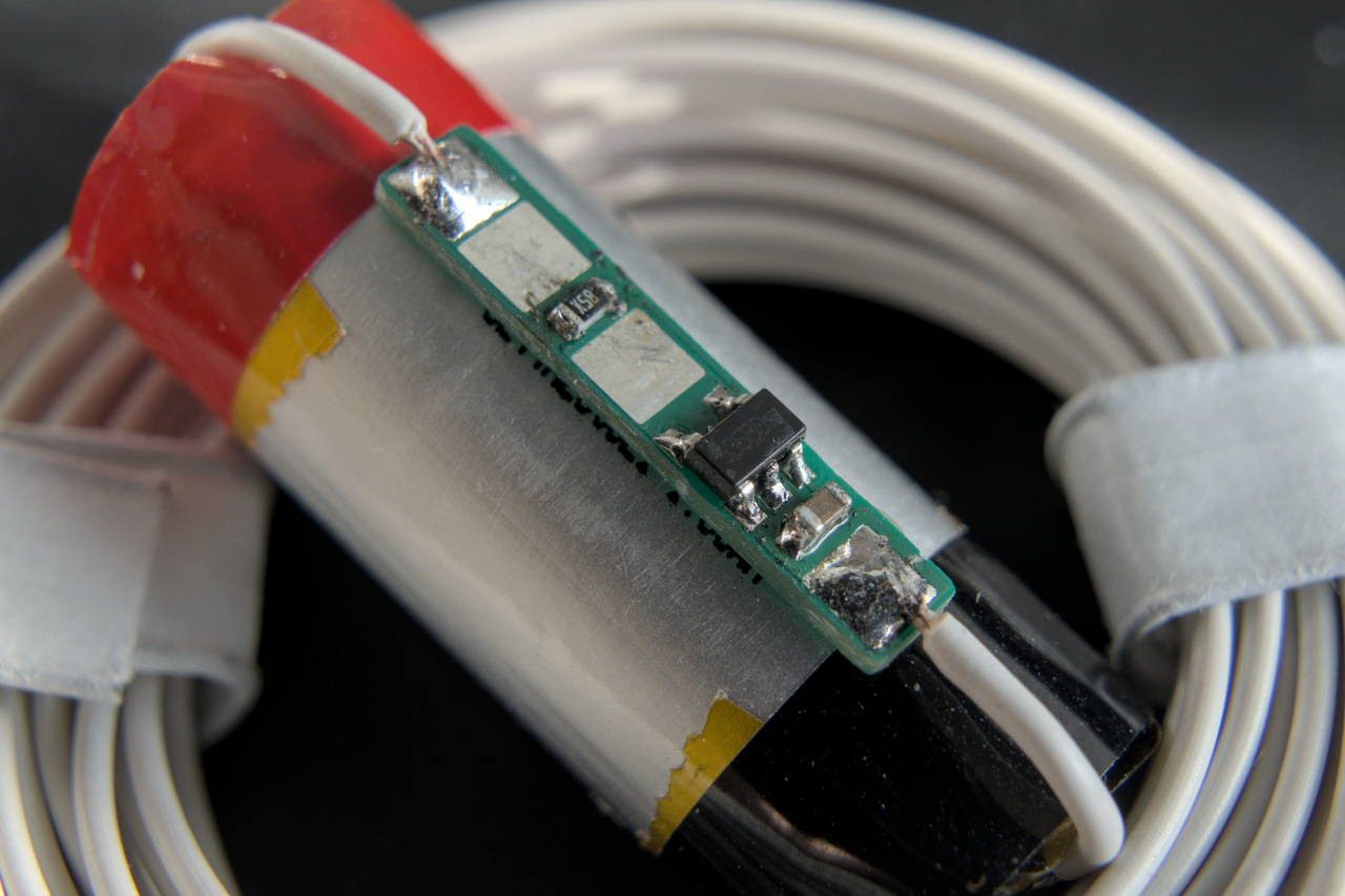
The design files of the small protection PCB in the photo at the top (with nothing more than the XB5358 and its supporting resistor and capacitor) can be found here.
Update August 4, 2025: The schematic diagrams above originally had the VM and GND swapped. Thanks to Jasper Devreker for noticing!