Charlieplexing Nixie Drivers
Nixies are great. Delightfully simple in their principle of operation and absolutely unmistakable in their aura. The hard-to-imitate aesthetics do come at a cost: they are a bit inconvenient to drive from modern electronics.
Many tried-and-proven nixie driver circuits can be found online. Using the classic 74141. With individual high-voltage transistors and shift registers. Or multiplexing the nixies to save on driver electronics? Multiplexing of nixies is a controversial topic: while the benefits are clear, many argue that nixies wear out faster due to the high current peaks when multiplexed.
This post isn’t about nixie multiplexing, though.
In theory
Instead, I’m talking about the driver transistors.

Compared to the usual nixie driver circuit, this one looks a bit odd at first:
- The emitters aren’t connected to ground. There is no ground anywhere. The emitters aren’t even directly connected to a microcontroller pin (which could function as ground), but instead have a series resistor.
- There is no load resistor at the high voltage supply: the tube’s anode is directly connected to +170 V.
- Not to mention the various connections of emitters and bases to four common lines.
Let’s begin unravelling this circuit by only looking at a single digit, let’s say the zero. If we ignore everything else, it’s pretty clear that the zero digit’s driver transistor is only going to become active when line A is driven high and line B is driven low by the microcontroller.
If that happens, our transistor’s base-emitter junction is forward-biased, and it starts allowing collector current to flow. There will be a voltage drop across the nixie tube (anode to cathode 0) large enough to strike the gas discharge. At that point, a current will flow from the high voltage supply through the tube’s plasma into the transistor’s collector and finally via the emitter, emitter resistor, line B, and microcontroller into ground.
Now, a soon as the tube is glowing, its voltage drop is dropping significantly from its trigger voltage. Continuing to drive it from the 170 V supply without a load resistor would usually result in a destructively large current through the cathode. However, in our case, the current through the tube also effects a voltage drop on the emitter resistor, reducing its base–emitter voltage, base current, and therefore collector current.
We have built a constant-current sink for each digit! The voltage which would usually drop on the load resistor inserted into the anode connection is now dropped on the transistor’s collector–emitter junction instead. The regulated current depends on the microcontroller’s IO voltage, the transistor’s base–emitter voltage and the emitter resistor’s value (the base resistor is largely irrelevant). For a microcontroller operating from 3.3 V, a 1 kΩ emitter resistor gives me a cathode current of about 2.6 mA, which is just correct for the nixies I want to drive.
Because each transistor conducts if and only if its base–emitter junction is forward-biased, we are free to connect two of those back-to-back, like I’ve done for digits 0 and 7 here. Since we can also set the microcontroller pins to high-impedance, we can make full use of a charlieplexing arrangement and connect N²–N driver transistors and cathodes to N microcontroller pins and resistors. For our four lines, that means we could actually drive twelve cathodes, if the tube had that many.
What if we want to turn all digits off? If we set all pins to high-Z, leakage currents will implant a logic high on every pin. Nothing bad happens, since no base current flows for any transistor and the microcontroller’s protection diodes limit the pin voltages, but we can play it safe and set all lines to low (or all lines to high) for the same effect.
A neat thing about this circuit is that it not only uses fewer microcontroller pins than a naïve, non-multiplexed, one-signal-per-cathode driver, but also fewer parts, since there is just one resistor per line and no anode resistor. The constant-current operation we get for free might also be beneficial if the high-voltage supply is not that well-regulated.
If you are wondering what to do when you need more than one digit: this circuit unfortunately can only directly handle one tube, since only a single transistor in the ‘matrix’ can conduct at a time. You could multiplex multiple tubes by either switching the anodes as well or enabling transistors from different tubes in sequence, but if you increase the per-tube current to compensate for the lower on-time, you will, at some point, run into the issue that the full cathode current has to be carried by the microcontroller pin. In any case, the safest bet is to duplicate this circuit for every tube, which still isn’t the worst deal.
In practice
To test the circuit, I used a QS30-1, some individual contacts (in lieu of a socket), and a small microcontroller board. When the driver transistors are soldered directly to the cathodes and the rest is connected using enamelled wire, the circuit looks a bit made up. I guess it is the unlikely large number of transistors compared to the passive components?
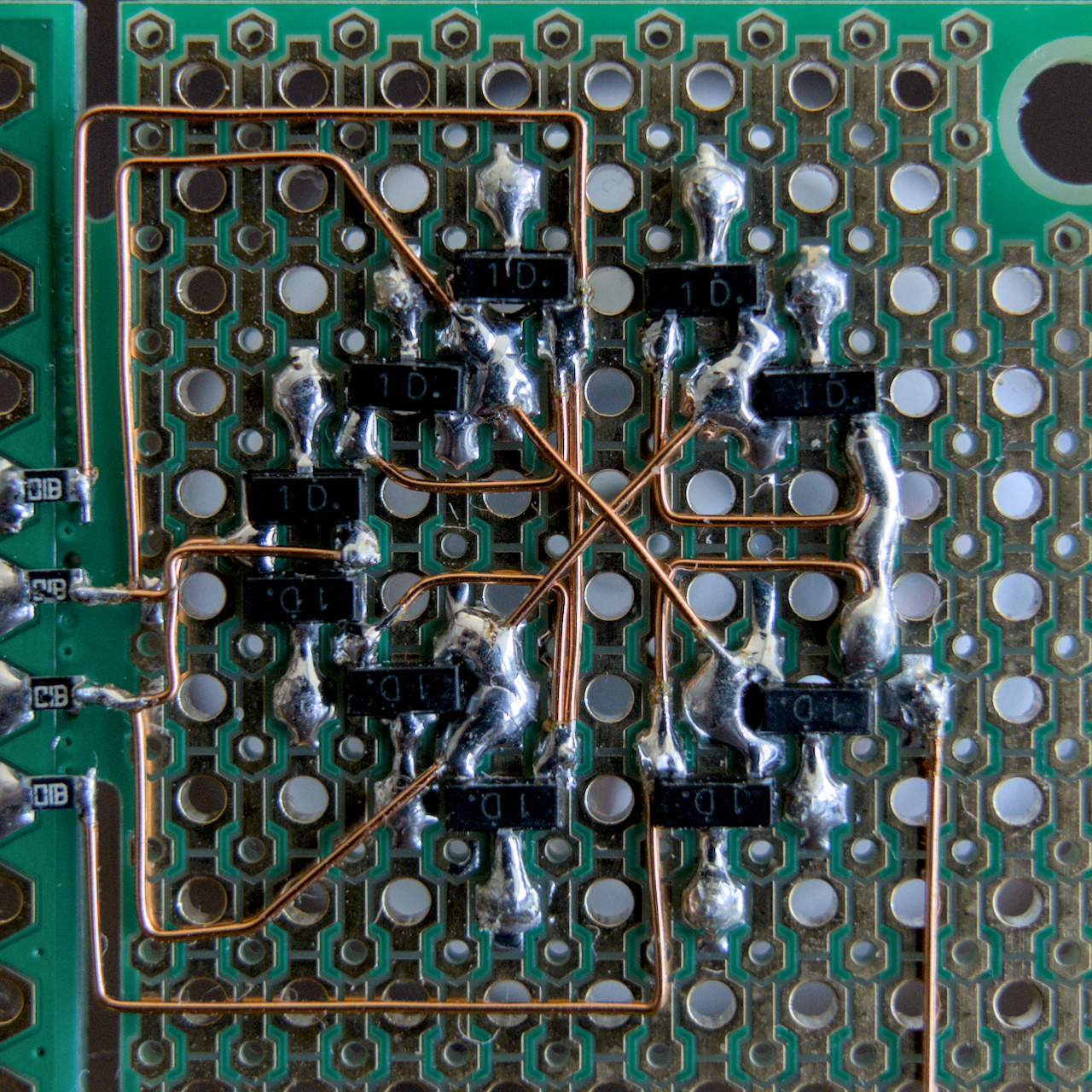
Immediately, one disadvantage of this configuration came to light. Because transistors are turned off by switching their bases’ microcontroller pins to high-Z, their large current gain can be a hindrance: any surface contamination leads to residual currents, which get amplified. In my case, I found that even flux residue could easily lead to ghosting.
After clean-up, however, it worked exactly as planned. My conclusion here is that this circuit is indeed suitable, but only if accumulation of dirt and dust on the PCB can be limited.
When writing this blog post, I also went looking for this or similar circuits—there is a long history of nixie drivers after all. I could find one report from 2003 describing, among others, the individual parts, that means constant-current drivers and the charlieplexing configuration, but I wasn’t able to find any mention of something similar getting actually built. If you know of any real-world realisation of some odd nixie driver like this, please get in touch! I’d be interested to know about others’ experiences.