USB-C to Micro-USB Adapters
I have a Seek thermal camera, which works by connecting it to a phone and using Seek’s app to display the image, take photos, etc. It’s an older model, from back when there were two variants, one with Micro-USB and one with Lightning. I’m on my third phone since I got it, which does not have a Micro-USB port any more. But it’s easy to get an adapter from USB-C, right?
Naturally, as we’ve come to expect with USB-C, if you just order an adapter which looks right, you will wind up with one which doesn’t work—or it does, and it’s not obvious what to look for when you want another one that works1. This is why I wanted to take this opportunity to focus on a tiny aspect of USB-C in practice.
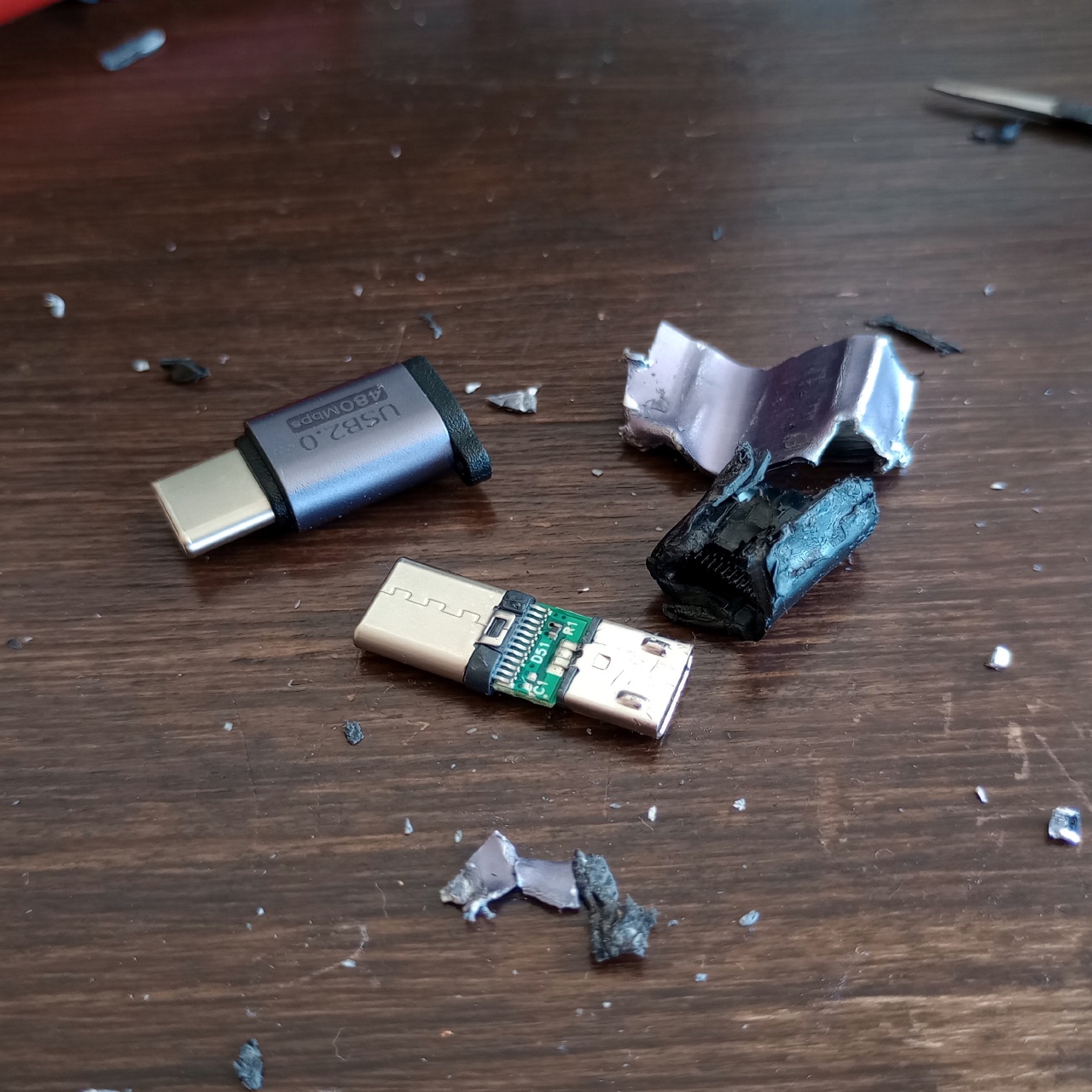
This note was prompted by me breaking my (perfectly fine) USB-C (male) to Micro-USB (female) adapter, ordering a new one which looked the same and getting a non-working one. Rather than ordering and trying adapters until I find one which works, I’d rather see if I could ‘fix’ the new one. I suspect my use case is pretty rare: the much more obvious use is ‘I want to use the Micro-USB cable I already have with my new USB-C product’, for which it does work. So the data lines are clearly there, so this should be fixable.
Let’s start with the (probably) more usual case, where the host connects to the Micro-USB side and the device to the USB-C side of the adapter and try to come up with an adapter from first principles. The device announces its presence to the host with a resistor on a data line (depending on the USB standard), so just connecting D+ and D− lets the host detect the connection. The device however expects the host to communicate its current supply capability through a pull-up on a CC line. This feature didn’t exist prior to USB-C, so an adapter will have to provide this resistor. A value of 56 kΩ means the device is not allowed to draw more than 500 mA, with which we’re on the safe side.

We’re only connecting one CC line, but this is fine, since the adapter has a USB-C plug and USB-C cables are only connecting one CC line, too. The problems frequently seen with USB-C devices cheaping out and and using only one CC resistor only affect devices and their pull-down resistors—nothing we have to worry about here.
For this direction, we’re done! But if the device is connected to the Micro-USB side, this adapter won’t work: a USB-C device announces its presence with a 5.1 kΩ pull-down on both CC lines, one of which gets connected via the cable to a CC line of the host. There’s no pull-down here. My phone won’t know I plugged anything in the Micro-USB socket and won’t start the enumeration.
We could just add a pull-down to the adapter, but this would present the adapter alone as a device itself and might also lead to issues when the Micro-USB socket is host-side. Also, the adapter’s 56 kΩ resistor we added for the other direction would be parallel to the host’s pull-up and will potentially skew the host’s current capability announcement.
It seems that adapter circuits can only ever work in one direction—how do we get out of this bind?
Before there was USB-C, USB On-The-Go allowed a device to use its connector for both host and device operation. Naturally, it had to know whether a device was connected or it had to present itself as a device. This is done using a fifth pin, ‘ID’, which is connected to ground for devices and left floating for hosts. An On-The-Go device can check whether the ID pin on its socket is shorted to ground; if it is, it operates as host for the connected device, if it isn’t, it presents itself as a device.
We can also use this pin in our adapter—and voilà: with a device connected to the Micro-USB connector, the adapter now has a 5.1 kΩ pull-down on a CC line2; if the device is attached to the USB-C side, and the ID pin is consequently left open, it sees a 56.1 kΩ pull-up. Perfect!

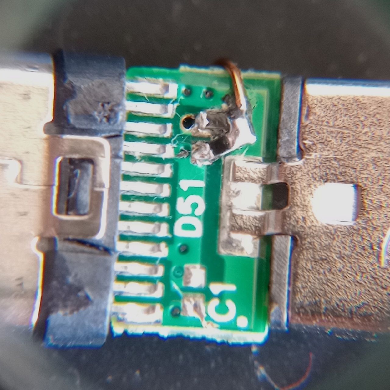
To get this circuit into the existing adapter, it is easy enough to pull the existing pull-up resistor off the PCB and solder in a series connection. The common node of both resistors can then be connected to the ID pin with a bodge wire. The fixed adapter would effortlessly fit into the original case—if it still existed.
-
No, including ‘OTG’ as a keyword does not help. ↩︎
-
Using only one CC line is still fine, since the adapter has a USB-C plug. If that were a socket, it would be an issue, since a cable could just not connect the pull-down to the host. I’m not sure such a clean and simple solution would be possible in this case at all. ↩︎