A Better STM32F0 Prototyping Experience
This project started when I was particularly annoyed by existing development board options and cheap Chinese PCB prototyping services were starting to emerge. Thus, the path forward was clear, but let’s start with the problems I was trying to solve.
When I’m talking about ‘development boards’, I mean boards like the Teensy models, Feather variants or blue pill: a PCB based laid out around a microcontroller containing very little extra circuitry; a ‘least common denominator’ of typical projects using that MCU, if you will. Evaluation boards with more interesting circuitry are great to get used to a microcontroller and its peripherals but lie beyond the scope of this post.
Development boards like these generally break out all useful MCU pins onto 0.1-inch headers and try to be as small as possible. This works out great for breadboarding or when you have ready-to-go modules for all your parts anyway. Getting the job done is as easy as it gets when you’re selecting your components based on the available modules and the available software libraries anyway.
Extra PCB space for prototyping is only sold as an add-on module, even though it would be, in my opinion, an extremely useful addition in general and not just for some fringe cases. Otherwise, as soon as you need even one external driver transistor, you’d have to decide whether to connect it with loose wire or to tack on some perfboard. Even if every component involved comes with its own little PCB, the whole assembly likely ends up as large, frail mess of wires, unless you want to limit yourself to your particular development board’s ecosystem.
Ergo, this project was started to help me keep small prototypes all in one place and sensibly resilient without the extra effort, while allowing maximum flexibility.
Design objectives
Before getting to the actual PCB layout, there need to be some concrete, tangible goals for the design. After the short rant above, here we are:
Goals
- Cost: The PCB should be as cheap as possible so you don’t have too feel bad about leaving it with a one-time experiment.
- Versatility: A good prototyping board isn’t designed with a specific purpose in mind. It shouldn’t limit you in what you’re doing with it.
- Self-sufficiency: One PCB should be enough for small prototypes. You shouldn’t have to add an extra perfboard or connect modules with jumper cables to get a simple job done.
- Extensibility: Simple projects should be simple, but complex prototypes should still be possible.
- Clarity: Getting started with a prototype should be as fast as possible, as should be debugging and measuring. No convoluted design for hard- or software.
- Small size: Keep it small, so it fits everywhere.
Non-goals
- Covering every single configuration and use case. Defaults should be sensible, but bodge wires are a natural component of prototypes and don’t have to be avoided at all costs.
- Mass production (at least at first). The idea was to ship a blank PCB or a kit. You would only solder what you needed for a prototype (further reducing the cost).
- Beginner-level solderability. While it isn’t supposed to be solderable only by experts, using 1206 components for everything would affect the overall size of the board while providing no benefit for the majority of users.
Design choices
That was a lot of talk about the general ideas and the honourable aim of the project. Now it’s time to narrow the design space down and try to fulfil our constraints.
The microcontroller
As the first (and most important) part, the central microcontroller was chosen to be a STM32F030F4P6, a 48 MHz ARM Cortex-M0 with 16 KiB flash and, amongst others, 2 KiB SRAM, one USART, one I2C, one SPI, nine ADC channels and four timers. With a small and manageable microcontroller like that, the board can become a cheap and easy solution for small prototypes, simple automation tasks, data logging, etc.
It’s deliberately a rather small device because I found it to be sufficient for a lot of stuff I do. Personally, I don’t really like to approach of directly going for a vastly overpowered microcontroller for every side project just because it’s a one-off thing and the slight additional cost doesn’t matter; instead I consider optimising the firmware and making it fit into a small device part of the fun. On top of that, with a small microcontroller, the board can be small and still won’t hold you back from doing everything with the controller you can possibly do. For instance, the decision which pins to break out is unnecessary because there’s simply enough space for all of them.
Form factor
Extremely small breakout boards for various microcontrollers are already plentiful enough and I didn’t want to compete with these. With a prototyping area as the key distinction, I had to strike a balance between a tiny PCB with insufficient space for other components and a large board which would be too unwieldy for most actual prototypes.
As mentioned in the very beginning, a key factor at the start of the project were special PCB prototyping offers. For this reason and the one outlined previously, I arrived at a quadratic 50 by 50 mm PCB pretty quickly. This proved to leave ample space for a prototyping area while still being small enough to be installed in actual prototypes.
Initial design
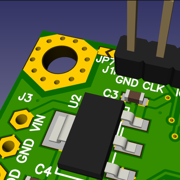
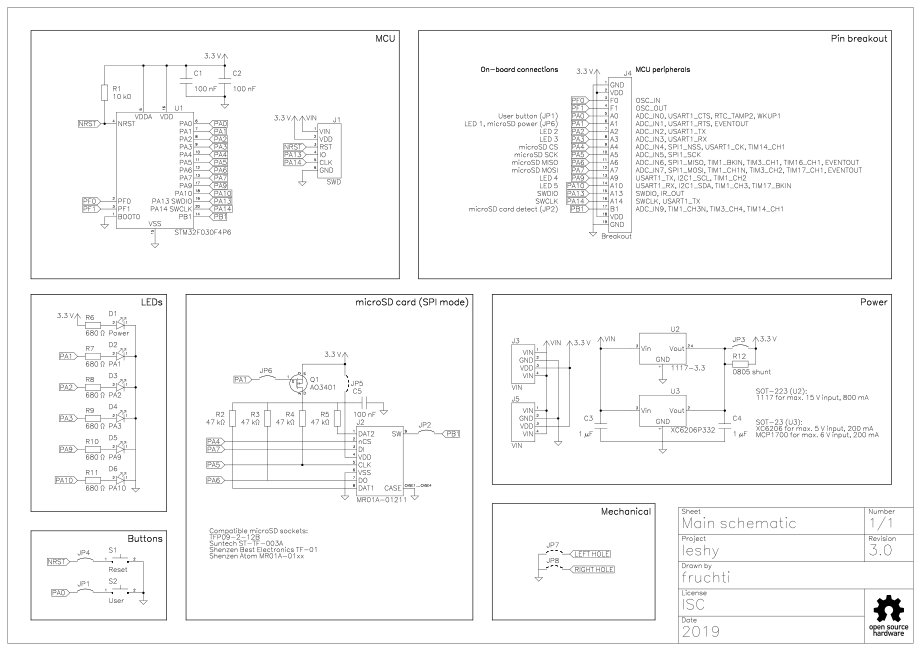
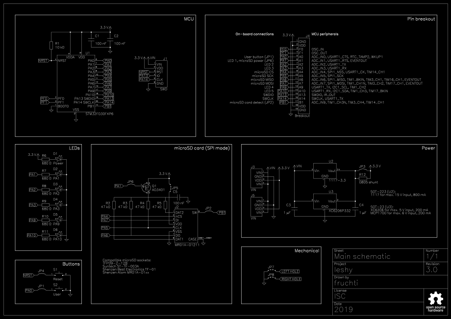
Here’s what I’ve come up with (all board renders in this post are generated with tracespace viewer, by the way):


I chose the name leshy, for less expensive STM32-hosting prototypes. Even though an evil forest spirit isn’t the best namesake for a friendly development board, that was the best (pronounceable) acronym I could come up with.
Notable design decisions
- The bottom part of the PCB is a 1.27 mm perfboard area which can be snapped off. The thought was to allow THT components just as well as SMT prototyping (the grid works out great for SOIC packages).
- Green solder mask was chosen deliberately: Unlike other colours, the traces are well-visible underneath it. Also, it seems to be a rather unique colour for a development board (even though, or probably because it’s the most standard colour for regular PCBs). But most importantly, it suits the name.
- There are five LEDs and one button connected to GPIOs. Their pins were carefully chosen so you can make the most of the MCU’s peripherals. LEDs are easy enough to just leave unpopulated in case you want to use the pin for something else.
- Two different LDO footprints can be populated: a MCP1700 (or pin-compatible, e.g. a XC6206) in SOT-23 for its low quiescent current or a 1117 in SOT-223 for more output current or a higher input voltage.
- There is no crystal, even though one could be connected between PF0 and PF1. The MCU’s internal oscillator is mostly precise enough, especially since the UART natively supports auto baud rate detection. Generally, I tend to run out of GPIOs rather than wanting a crystal oscillator, so keeping them available externally had higher priority.
- Jumpers are provided for everything where it would make sense to connect it to some other pin, like the pushbutton. As it’s thought to be a ‘place only what you need’ PCB, they are shorted with a narrow trace by default. If you need to change a connection, it’s easy enough to open it up with an scalpel.
- The choice to include a microSD socket might seem odd at first. It’s tremendously useful for data logging applications though and SD or microSD sockets are always inconvenient to solder onto perfboard. In contrast to, for example, FFC connectors for display modules there is only one pinout to consider, too. The footprint is compatible with a number of sockets available from Chinese sellers (e.g. TFP09-2-12B, MTCONN MCTF-0403, Atom MR01A-01211, Suntech ST-TF-003A, Shenzen Best TF-01).
- The SWD connector also includes a connection to the reset pin. This enables automated programming under reset, which is necessary when SWDIO and/or SWCLK are used as GPIOs.
- It’s not breadboard compatible as-is but can be made so by leaving out some pins. Otherwise, the breadboard would short out the supply voltage. All pins are on a 0.1 inch grid, though.
- Attention was paid to leave as much space as possible around mounting holes. A lot of off-the-shelf breakout boards only have very limited clearance there and sometimes even a M3 screw’s head is too large to fit.
Second revision
When I started running out of PCBs, I took the opportunity to optimise the design a bit. Not too much was changed, though:
- The reset switch isn’t necessary most of the time. Consequently, I added J4 so it can be disconnected from the MCU’s NRST pin and used for other purposes.
- SD cards can draw quite a bit of power, even in standby. Thus, I added a p-Channel MOSFET (Q1) to cut the microSD card’s power supply if it isn’t needed. The solder jumpers J5 and J6 were added to short the MOSFET (if it isn’t installed) and to re-route its gate to another pin, respectively.
- Additional silkscreen text was added: The back side contained information which pins were connected to the microSD socket and also what each solder jumper did.
- The board now actually shows its name. Above it, I added a white silkscreen rectangle for custom marking (e.g. what prototype the board is supposed to be in).

Apart from that, the PCB stayed the same:


Revision 3: a redesign
The last two revisions had a few annoyances:
- Although great in theory for SMD soldering, the prototyping field had its issues: Due to the low clearances, it was prone to bridging and the solder liked to ‘fall through’ the plated holes, accumulating on the bottom. These problems are, however, inevitable for the given design: Since I wanted compatibility with as many THT parts as possible, I couldn’t just shrink the holes to decrease the tendency for the solder to flow through to the other side and to increase the clearances between the pads.
- Resistors and capacitors used the same footprint. This doesn’t matter too much for hand soldering, but can be an issue if the board should be reflow-soldered.
- There was only one connection for the input voltage. It would be useful to have at least another one closer to the prototyping area.
Since the last revision, I had also moved away from KiCad to Horizon EDA. While still in a beta stage, it is already more comfortable than other EDA tools in my opinion. I decided to redo the complete design in Horizon, which allowed me to pull some tricks which would have been inconvenient to implement in KiCad.
As the first problem was the most important one, I started the redesign with this one. I had come across the ALio prototyping platform, which looked like a solution (and a strict improvement on the current prototyping area). The staggered holes allowed for bigger hole diameters in the ‘base grid’ while clearances could be increased at the same time. The non-plated smaller ‘vias’ lower the risk of solder seeping through for SMD parts. On top of that, the horizontal and vertical connections via solder bridges should be a very nice addition.
I created a parametrisable design inspired by the ALio boards. I didn’t exactly follow the original’s geometry. Most importantly, the clearances between pads aren’t uniform. Instead, I increased them outside the designated ‘solder jumper’ areas.
Apart from the supply current measurement jumper (J3, ‘IDD’ in the previous revisions), the new layout is mechanically and pin-compatible. Still, a lot of improvements were possible:
-
There are a lot more connections to the supply voltages. There are pads for VIN closer to the perfboard area and supplying 3.3 V directly is now more convenient, too. The power input connector J3 (previously K3) is also mirrored on the other side as J5 now and the SWD connector got a VIN pin to allow supplying 5 V via a attached debugger.
-
The jumpers are no longer shorted by default. Instead, they were exchanged for a footprint which makes both closing them with a solder blob and placing a 0603 0 Ω resistor as convenient as possible.
-
Pads were added to the top half’s mounting holes. Each one got its own solder jumper in case you want to ground the PCB via mounting screws.
-
The two pushbuttons were exchanged for slightly smaller ones, which also are easier to press.
-
All solder jumpers between microcontroller pins and on-board components are now on the front of the PCB and as close together as possible to make swapping pins easier.
-
The IDD jumper was replaced by a solder jumper. I rarely needed it and didn’t find the occupied PCB space to be justified. I placed a 0805 resistor footprint (R12) right next to it, which could be useful for a shunt.
-
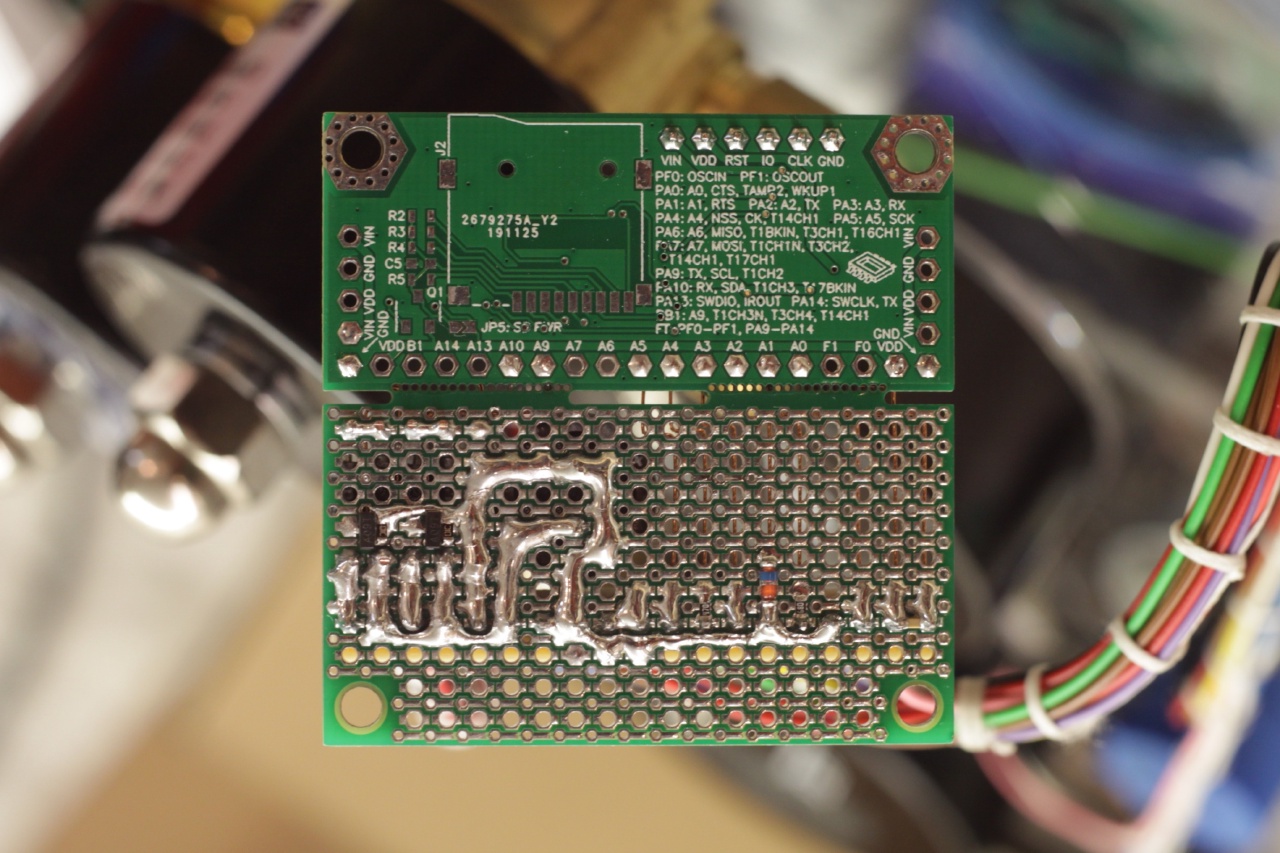
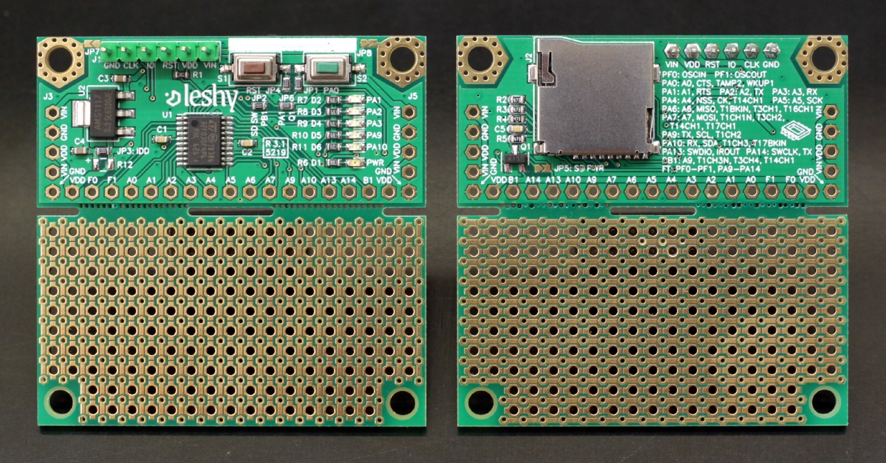
Silkscreen documentation has been extended quite a bit: The labels for the microSD card pins added in revision 2.0 weren’t all that useful in practice. After all, you’d only need this information once, when implementing a memory card library. Other information would have been more useful: I still needed to refer to the schematic basically every time I used one of these boards.
In the new revision I was able to add all1 alternate functions for all pins to the board’s back side by abbreviating the peripherals (ADC → ‘A’, TIM → ‘T’, etc.). The last line indicates which pins are five-volt tolerant. The solder jumpers now have labels right next to them, showing what they connect.
Now you shouldn’t have to look at the schematic all that often when deciding what to connect where.
-
Vias are now untented (except for ground vias). This is mostly irrelevant, but untented vias can provide some extra probing/bodging points in a pinch.
-
The white area for annotations was moved to just above the buttons. Now it can just as well be used to label the buttons.
-
Small details were fixed: The resistor and capacitor footprints should be correct now, the SWD connector’s pins are now labelled on the back, too, and the microSD socket got proper keepouts.
Revision 3.1
Revision 3.1 is mostly identical to 3.0. The only change was to move some more vias out of the way of the extensive silkscreen to make it more readable. Here’s what it looks like:


Software
The STM32F030 is a pretty small controller and naturally I prefer its code to be rather close to the hardware. Its peripherals don’t include anything complicated, so it’s well usable without a hardware abstraction layer or other support libraries.
Nevertheless, it’s nice to have a starting point and some code to reuse. Thus, whenever I come across a piece of code which might be of general use, I add a little example to the repository’s demo directory.
In use
I want to conclude this short write-up with some examples to highlight leshy’s capabilities for fast and easy prototyping. Most of these can be found in the aforementioned demo directory.
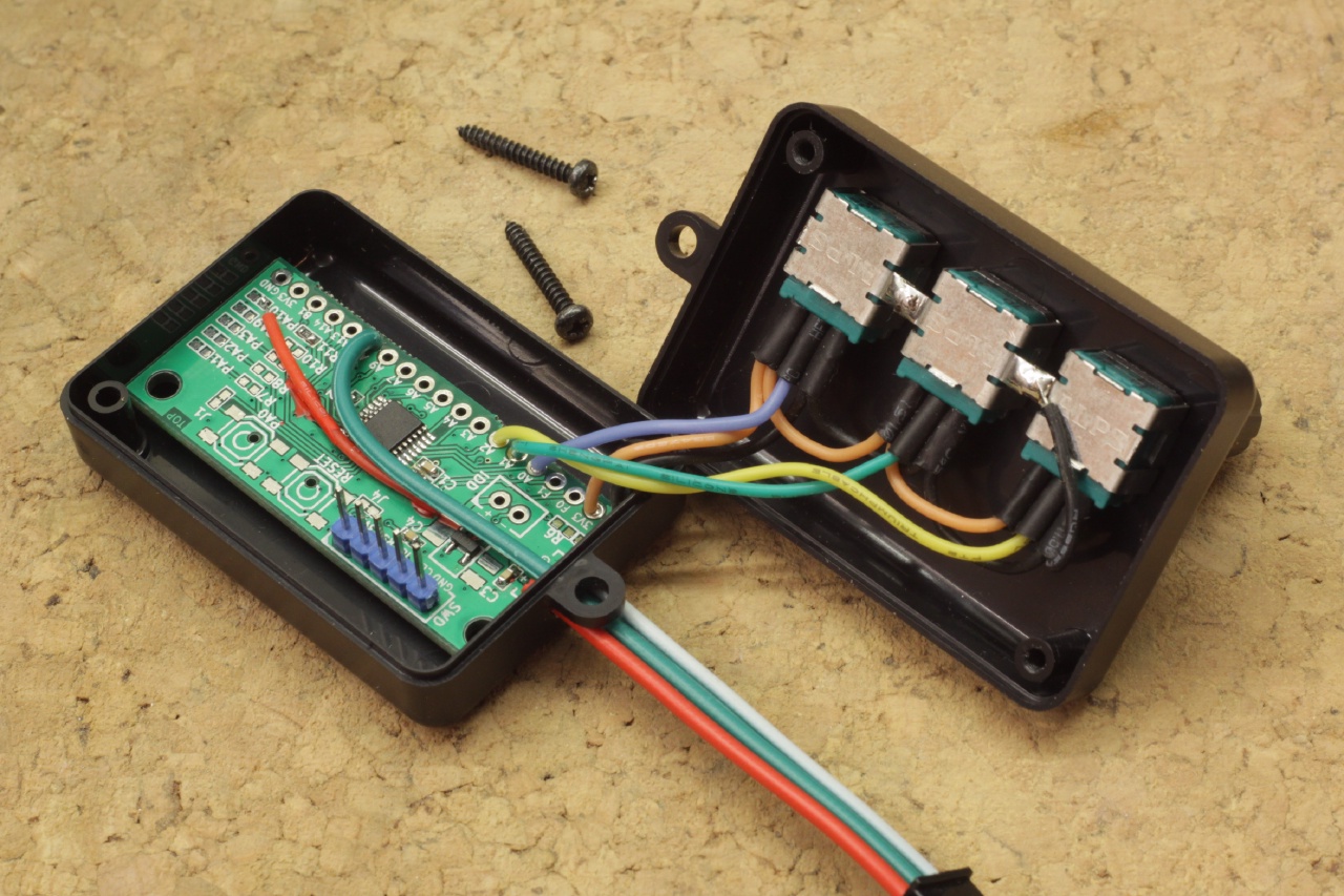
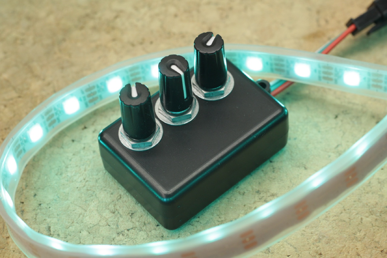
Minimal circuitry in a small case
Not much is necessary to drive WS2812B or SK6812 LEDs: a single pullup for a five volt tolerant pin is enough. I reused a resistor footprint originally present for one of the on-board LEDs. That way, the prototyping area can be snapped off and the leshy fits into a pretty small case. With three potentiometers, a controller to set H, S, and V is done very quickly:
Simple state machines
A lot of automation tasks just need a few components for signal conditioning and driving external devices. This paste dispenser timer just needed two MOSFETs for driving solenoid coils and a few protection diodes:
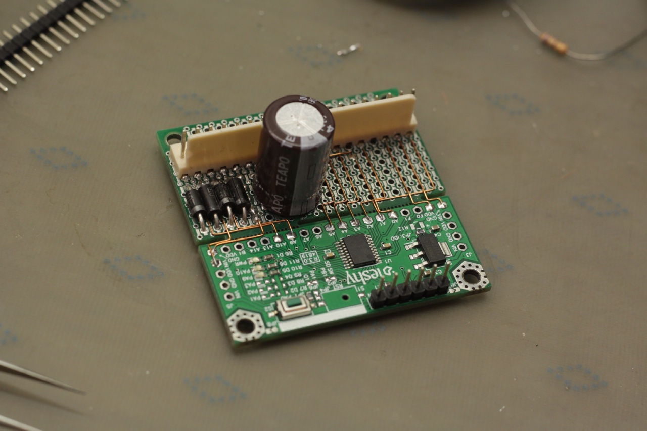
A lot can fit
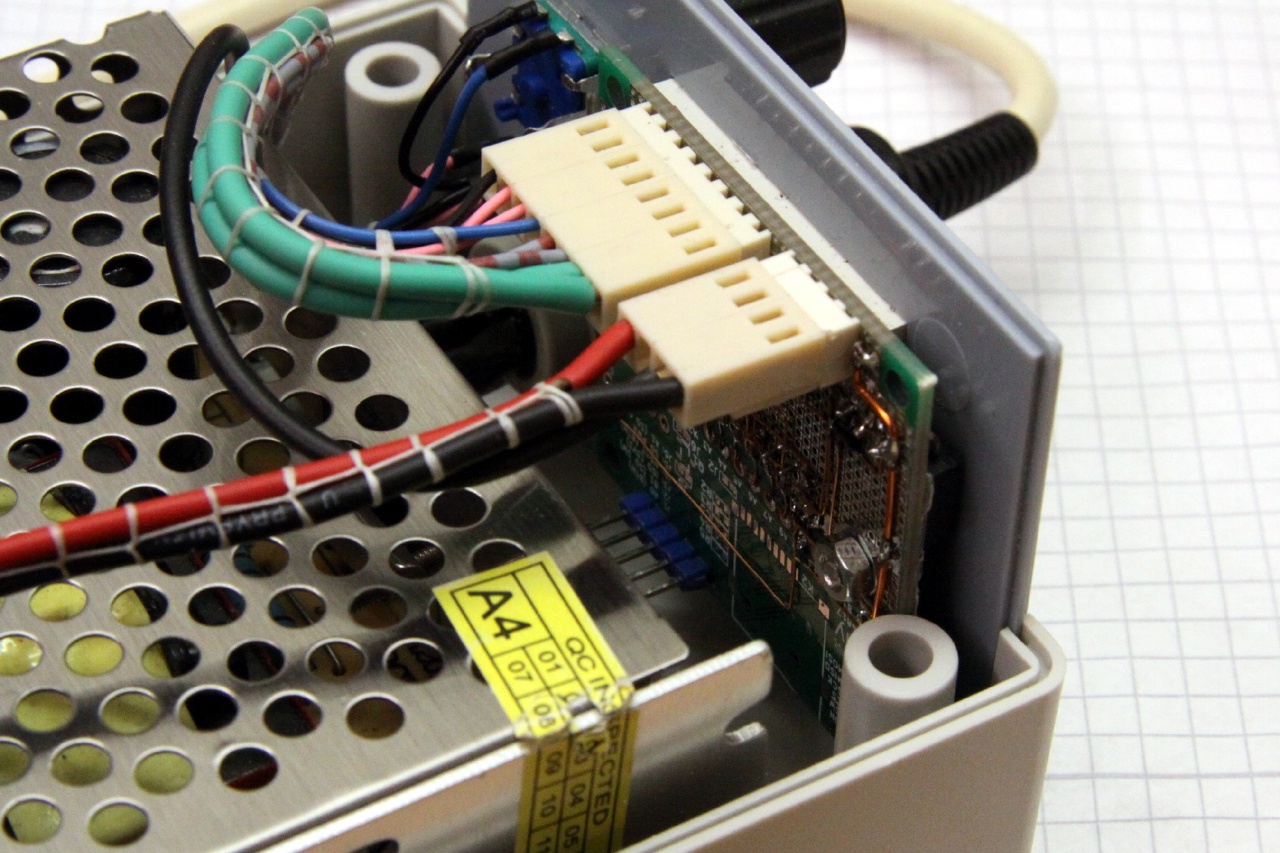
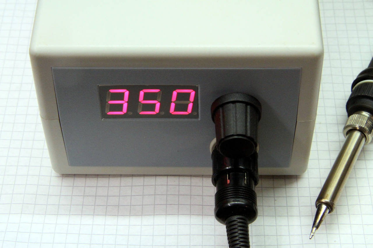
I needed a simple controller for a Hakko 907 soldering iron and a straight-forward solution was to add a seven segment display, a rotary encoder and a driving MOSFET to a microcontroller board. Everything apart from the rotary encoder and the circular connector fits directly onto the prototyping area. Code and schematic can be found on GitHub.
Wrap-up
Having used these boards in lots of different projects, I’d consider the project a success. While there probably are still some little details to be fixed, they are already a lot more convenient than other existing solutions. For my, a leshy nicely fits into a niche between proof-of-concepts where I can stay within one ecosystem and use off-the-shelf modules, and less impromptu projects where I’d design and etch/order a PCB.
I might expand on this idea and lay out development boards in the same form factor but with different microcontrollers. Promising candidates could be the ESP8266 for WiFi prototypes, the ATSAMD11 series, which would allow USB connectivity, or STM8 microcontrollers for testing very low cost designs.
Links
Schematics, layout and firmware examples can be found in the project’s GitHub repository. Some prose of mine on the project’s previous revisions can be found on leshy’s Hackaday.io page.
-
Well, almost all. I had to skip the EVENTOUT pins but they aren’t all that useful anyway. ↩︎