Please Do Not Water This Tree
About two years ago, I made a little LED tree as a gift. An extremely simple design with 17 white 0603 LEDs soldered to magnet wire, twisted and bent to make branches, and combined them to a small LED bonsai. Electrically, all LEDs are wired in parallel and connected to 4.5 V via an LDR. This lets the tree react to the ambient brightness and helps it to great battery life.


In fact, it is still glowing nicely with its first set of batteries! This most basic circuit combines a remarkably natural analogue brightness control with efficient white LEDs, so long battery life isn’t too surprising. Still, I didn’t quite expect a battery life this long.
This blog post isn’t about this particular set of entangled magnet wires and LEDs, however. It’s about another bigger, tanglier mess of enamelled wire and LEDs.
The plan
It started when I found out I could get improbably small RGB LEDs. I immediately wanted to one-up my last LED tree. Let’s see where I could take it, shall we?
Using RGB LEDs of course would mean retiring the superb efficiency, but would allow for more impressive visuals. And, of course, the mere challenge of using these tiny LEDs in a circuit sculpture itself was quite appealing. This one was going to be a gift as well, but that doesn’t mean I couldn’t have some fun building it. Crucially, I didn’t have a strict deadline (this endeavour wasn’t suitable for a last-minute gift) so I was able to experiment a bit.
This post goes into some design decisions which made the technical aspects as interesting as the end result, at least in my opinion. It also covers some tricks I used to avoid going mad while dealing with the touchy rats-nest of wires making up the tree’s branches and roots.
Hardware
While I actually wrote a software proof-of-concept first to make sure I could pull everything off with the hardware I imagined, this post reads nicer if I start with the craftwork and slowly work my way towards the driving electronics and software.
Soldering LEDs to wires
As basic as it may sound, but the first, and perhaps most crucial step, is sticking blossoms onto branches. Thankfully, the LEDs linked above hold up under soldering temperatures quite well; otherwise this project probably wouldn’t have been possible at all.
Still, what isn’t too hard for basic white LEDs is a lot more involved for RGB LEDs. When soldering a single colour LED’s two pins to wires, only so much can go wrong: you can have a short, open circuit or swapped pins, all of which are immediately obvious when testing with a multimeter from the other end. With four pins, there are a lot more failure modes; manually probing everything until each LED is soldered correctly wasn’t going to cut it.
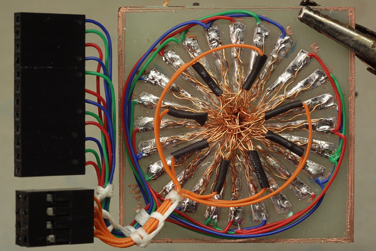
Instead, I made a simple test signal generator I could connect to one end of the cable. The circuit below ensures that all three colours independently either light up or go out if an RGB LED is connected to its four outputs, no matter how exactly. This means all possible faults are immediately detectable: if one colour is missing, there is an open circuit—if two are always lit at the same time, there is a short.

In practice, I’d twist four magnet wires together with a cordless drill and connect one end to the tester circuit. I could then spread out and tin the wires on the other end, solder an LED to it, and cut off the correct length once it was fixed properly. After that I’d repeat the process until there was no cable left and I had to twist a new one.


Making sticks and branches
With the LEDs soldered, I dipped all ‘blossoms’ into epoxy to protect the solder joints from stresses while bending branches. I probably wouldn’t do this again, though: it cannot protect the LEDs by 100% and if they do fail, the epoxy coating makes rework absolutely impossible. With tightly twisted wires, the solder joints are actually pretty sturdy and don’t need too much additional protection, so I’d prefer applying a protective coat once the whole tree is done.


Matrix configuration
Now, if you look at the trunk in the last picture you’ll probably dread the task of separating all those 128 wires again. While I could just solder all reds, greens, and blues in parallel again, I wanted to have all possibilities this time—I wanted to be able to control individual LEDs. There really wasn’t no way around separating and matching individual strands.
But I didn’t use 32 LEDs for no reason. I chose this number because I could neatly wire them up as a matrix with eight rows and twelve columns. To keep the wiring manageable, I quickly printed a PCB with a pattern for the columns:


The sectors are in turn R, G, and B LED cathodes. There are 24 of them: two sectors for each columns so I only have to solder four wires to each one instead of eight. The common anodes will be soldered freely floating in mid-air.
Wiring up the matrix went as follows: I started with the outermost ‘twigs’ from the trunk and unraveled each one, bent the anode wire upwards and soldered the cathodes to arbitrary R/G/B baseplate sectors which didn’t already have 4 wires. It’s only really important here to keep the three cathodes of each LED together as one group, all other connections can be made in the most practical way.
With all cathodes fixed to the sectors, I connected two sectors of the same colour to a column line. Then I could grab four random anodes (which is why I bent them upwards, out of my way, before) and call them a row line. Because the columns provide more than enough mechanical stability, the row bundles were soldered without any additional support.
Perfect! We now have an LED matrix which looks like a tree, fixed to a nice baseplate with wires coming out of the bottom. The individual pixels are spread out pretty much randomly, but fixing this in software later is much easier than paying attention to each and every LED and its row and column index.
LED driver electronics
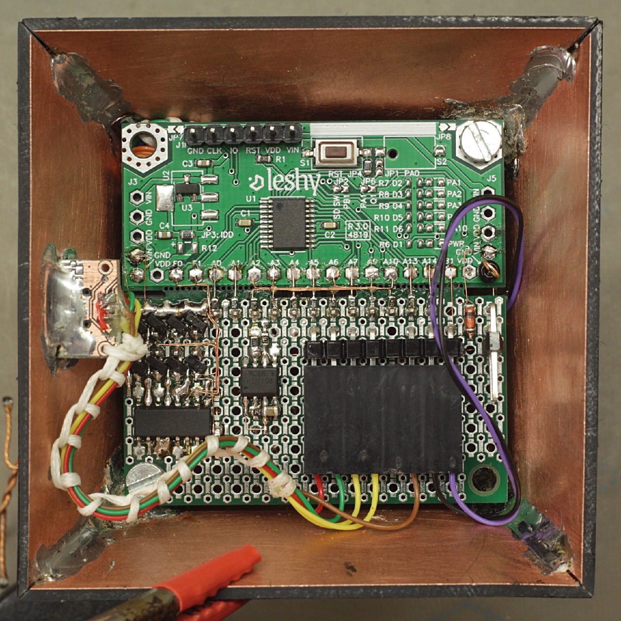
For driving the LED matrix, I used a small ARM Cortex-M0 microcontroller (here the ‘keeping things interesting’ mentioned in the beginning slowly comes into play). The rows of the matrix are driven using a shift register because there wouldn’t be enough pins otherwise.

Everything fits onto last blog post’s prototyping PCB. I used a blank PCB and only populated what was needed; e.g., there is no microSD connector (which would have mashed with the column connector).
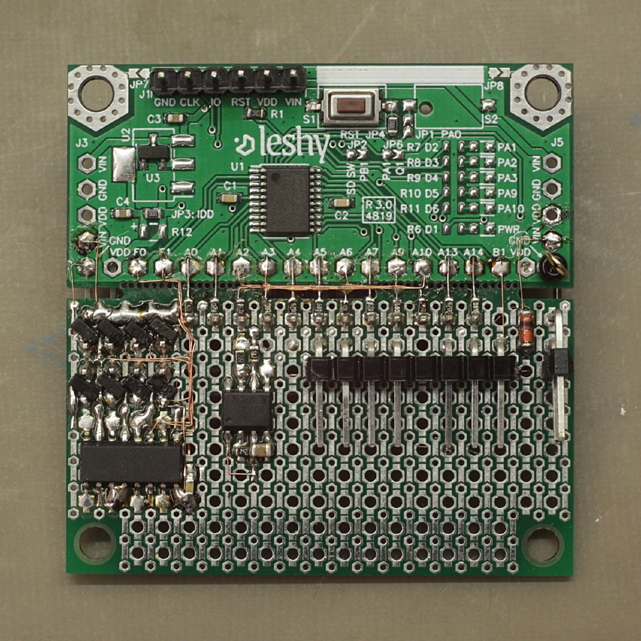
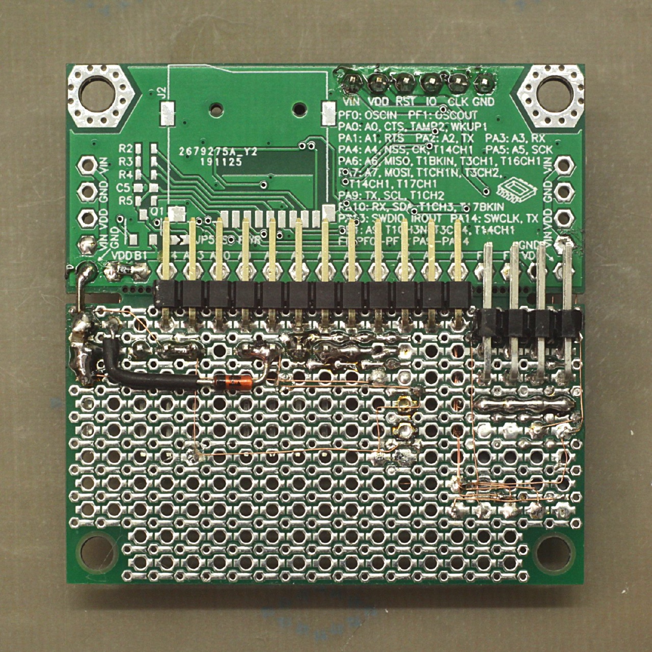
With the whole port A occupied for driving the columns, the SWD pins couldn’t be left free. This sadly means no debugging is possible1, but the MCU can at least still be flashed by connecting under reset.
Power management
In the pictures above you might have spotted a few parts unaccounted so far: an SO-8 and two diodes—which really is all there is to the power management in this project. Power can either be supplied with a Micro-USB jack or by a single-cell LiIon battery, for which a charging circuit is also included.

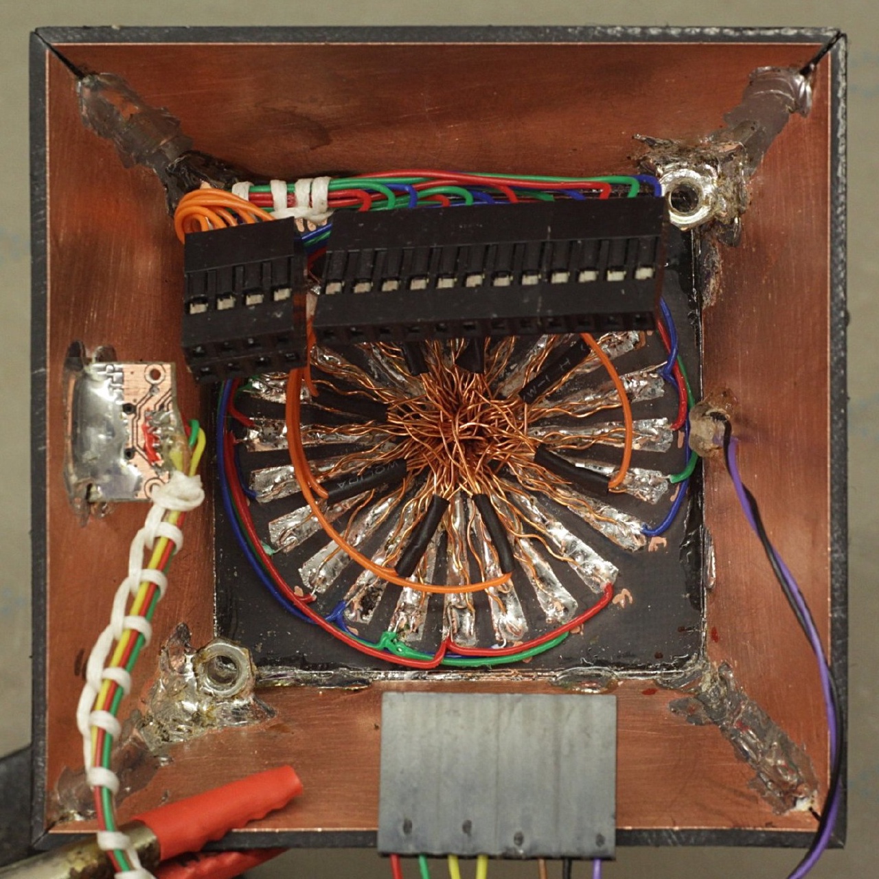
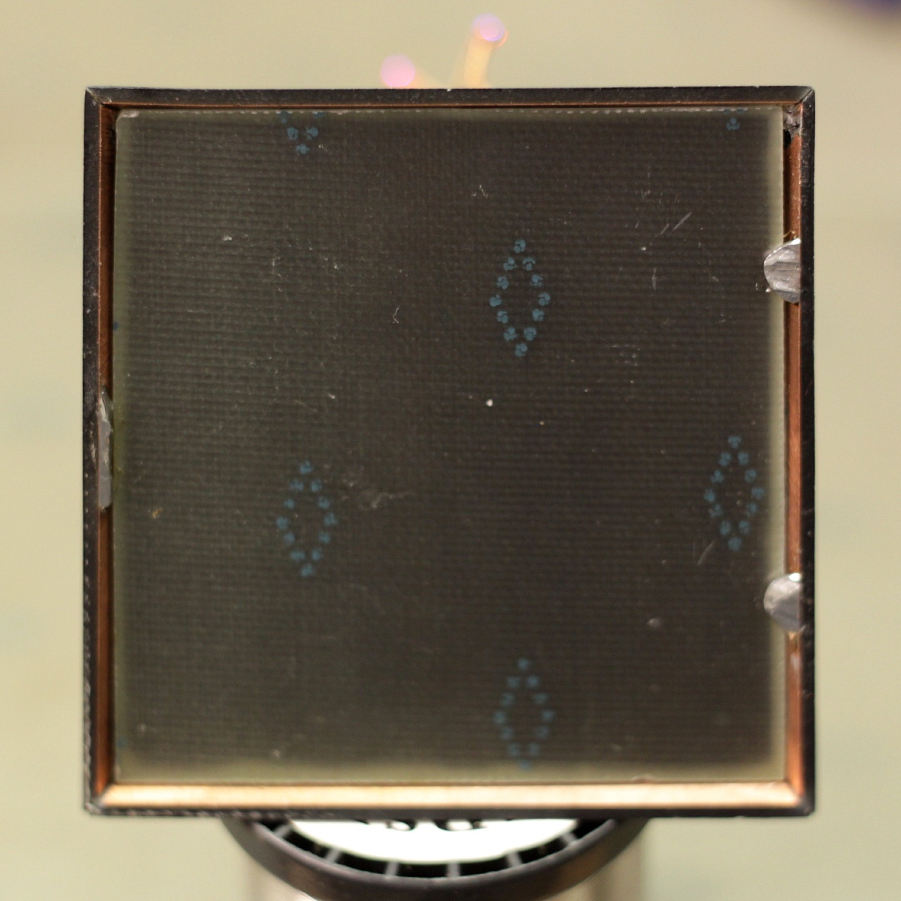
Case
The case, a simple pyramid base, is made from PCB material. The matrix baseplate was just soldered to the sides and formed the top.

Software
Using a pretty small MCU to control the LEDs directly of course makes the software more interesting, as there naturally weren’t enough hardware pulse-width modulation (PWM) channels for all 12 columns. All the timing-critical signals for the brightness modulation will have to be driven from software. In addition, the software will also have to do other things, like measuring ambient brightness and animating the LED colours.
The goal here were smooth animations while having global brightness control. With a basic gamma correction2, I wanted at least 12 bits of resolution so the brightness steps weren’t visible.
Some sort of PWM
12 bits are lot when you want a high refresh rate while scanning 8 matrix rows to keep the tree flicker-free—with no hardware PWM generation, at least. It probably would have been possible with a naïve counter/compare software PWM implementation, with a short blank for all computation other than just generating PWM signals. I went for a different route.

The idea of binary code modulation (BCM) is to split a PWM signal’s period into sensible chunks. By using powers of two as lengths, any cumulative on-time can be achieved by turning the signal on for selected ‘chunks’.
Each bit position corresponds directly to one of these chunks. For example, in the 5-bit case drawn above, a binary value 10011 (decimal 19), would have the signal on for 16 ‘ticks’, off for 8 + 4 ticks and on for 2 + 1 ticks. That’s a total on-time of 19 ticks (in a 31-tick cycle), exactly as we wanted.
From an implementation perspective, this is a lot easier to generate than a conventional PWM signal: instead of having to determine the output values of all channels each clock cycle with a comparison for each one, the bits are already there, they just need to be issued at the right times. Since the time slots are the same for all channels, the values can be easily precomputed and all put out in parallel.
An efficient BCM implementation
The firmware makes heavy use of the microcontroller’s direct memory access (DMA), which moves around data between memory and/or peripherals in the background, with no additional CPU load (apart from an initial set-up). Here, the DMA mainly moves 16-bit words from an array stored in the MCU’s RAM to the output register of the GPIO port connected to the LEDs, thus setting all LEDs to their new values at once.
This array is precomputed based on the brightness values and contains bit 0 of every value, then, as a next value, bit 1 of every LED’s brightness, and so forth. This handles the output of the on-off-sequence, neatly for all columns in parallel, without the need for much CPU interaction.
But how to get the timing right? On its own, the DMA could transfer the data as fast as possible, which wouldn’t help much with our wish for precisely controlled bit weights: all bit slots would have the same length. Luckily, the DMA can be triggered by a timer, which counts up and emits a DMA request once it hits a predefined value, i.e. after a specific time.
To get the different bit lengths for all positions, another DMA request is needed: triggered just after the DMA transfer to the output pins, it reconfigures the timer itself with the next bit timing, from a table with the power-of-two bit lengths. So this part, too, can be done completely in the background.
After one BCM cycle, which ends with the DMA turning all outputs off, an interrupt is generated. In its handler, the shift register gets a pulse so the signals for the next row can be generated. This could be generated by DMA, too, but at this point the CPU load is no longer critical.
Note that there is a slight delay from the timer generating an event to the DMA servicing it and setting the outputs. However, since the outputs are turned on and off only by the DMA and this additional delay is always the same, it does not appear as some offset you’d have to take into account. It would, however, be a problem if we had other jobs for the DMA. If the system did, for example, use the DMA to fetch communication data, this more or less random extra load would lead to visible jitter because the DMA might be stuck transferring data bytes when a request from the BCM timer comes in. In other words, the system only works because we’re not using the DMA for anything else.
As a small exception, the four lowest-value, and thus shortest, bits are generated by some inline assembly instead of the DMA. The least-significant bit is only two clock cycles long and the 16 cycles of bit 3 would still choke up the timer/DMA system because it won’t be able to keep up, with all its transfers.
Brightness control
If all LEDs ran at full brightness all day, the battery wouldn’t last too long; having an overly bright tree at dusk wouldn’t look to nice anyway. Thus, some automatic brightness adjustment is necessary. For the sensor, I simply glued a SFH320 phototransistor to a hole in the case and connected it to PB1 (the only pin still free at this point).
At first, I simply wanted to use a pull-up resistor and determine the brightness with the STM32’s ADC (the eagle-eyed among you might be able to spot the 0603 resistor which was still there when I took the PCB photos). However, I ended up soldering a 10 nF capacitor in parallel to the phototransistor, skipping the pull-up. By measuring the ambient brightness using the discharge time of the capacitor it is easier to cover a large dynamic range, because the timing can be changed in software whereas the value of a resistor cannot.
The software uses the exact same procedure as when using a reverse-biased LED as a light sensor (usually without the external capacitor, because the photocurrent is a lot smaller for an LED). The timing might be a little different, but with a readjustment of the brightness limits, an LED with its cathode connected to PB1 and its anode to ground should be a drop-in replacement.
Bringing order into chaos
We’re moving closer to the topic of adding actual animations to the 3D LED matrix. However, there is still one topic uncovered: for any visual effect other than a random twinkle pattern, for anything the position of the LEDs in space actually matters, I’d have to figure out where each pixel in the frame buffer actually went in the physical world.
Earlier I said it would be a lot easier to add another indirection the LED indexing in software than to wire up the matrix in a geometrically controlled way. While this is true, figuring out this mapping is still a bit of work. Without in-circuit debugging I couldn’t change pixel data while the software is running and without any pins free as inputs, it’s not possible to manually click through positions with a button.
I briefly pondered writing a simple UART transmitter on top of the LED matrix driver: each LED would send its array index, which I could then pick up with an optical receiver, taking notes as I probed around. In the end, I went for a simpler test pattern, which would blink at a visible rate, while using different colours as an additional distinguishing mark. Here’s my (rather hacky) code I used for this:
unsigned int counter = 0;
const unsigned int blink_period = 1000;
const unsigned int group_size = 6;
while(1)
{
    if(LED_FrameFlag)
    {
        memset(LED_PixelData, 0, sizeof(LED_PixelData));

        for(unsigned int i = 0; i < LED_COUNT; i++)
        {
            uint8_t brightness = 0;
            if((counter / blink_period) <= (i % group_size))
            {
                if(counter / (blink_period / 2) % 2)
                {
                    brightness = 30;
                }
            }

            switch(i / group_size)
            {
                case 0:
                    LED_PixelData[i].r = brightness;
                    break;
                case 1:
                    LED_PixelData[i].g = brightness;
                    break;
                case 2:
                    LED_PixelData[i].b = brightness;
                    break;
                case 3:
                    LED_PixelData[i].r = brightness;
                    LED_PixelData[i].g = brightness;
                    break;
                case 4:
                    LED_PixelData[i].g = brightness;
                    LED_PixelData[i].b = brightness;
                    break;
                case 5:
                    LED_PixelData[i].b = brightness;
                    LED_PixelData[i].r = brightness;
                    break;
            }

            counter++;
            if(counter > blink_period * (group_size + 2))
            {
                counter = 0;
            }
        }

        LED_FrameFlag = false;
        LED_Commit();
    }
}
With the blinking tree before me, I could then watch the pattern for each LED (in the order I wanted to have them in the end), and put down its index into a new array.
const unsigned int Animation_LEDOrder[LED_COUNT] =
{
    // Red
     0,  1,  2,  3,  4,  5,
    // Green
     6,  7,  8,  9, 10, 11,
    // Blue
    12, 13, 14, 15, 16, 17,
    // Yellow
    18, 19, 20, 21, 22, 23,
    // Cyan
    24, 25, 26, 27, 28, 29,
    // Fuchsia
    30, 31
};For the visuals I had in mind, this 1-D mapping was absolutely enough, but the process would work just as well in higher dimensions. You could, for example, film the blinking from above, overlay a grid, and give each LED two coordinates, if you wanted to.
Animation
From the beginning, I wanted the animation to be very subtle. Very subtle. Nothing flashy, no in-your-face bling-bling, no erratic patterns. A simple, slowly animated gradient from top to bottom was enough for me.
For a gradient in HSV space, with a ‘top hue’ and ‘bottom hue’ with constant saturation and value (which would be handled by the brightness control), I precomputed a lookup-table with some Python:
#!/usr/bin/env python

from colorsys import hsv_to_rgb

LUT_SIZE = 256
SATURATION = 0.8
VALUE = 1
RESOLUTION = 12     # in bits

print('const LED_Colour_t Animation_ColourLUT[] =')
print('{')
for i in range(LUT_SIZE):
    h = i / LUT_SIZE
    rgb = hsv_to_rgb(h, SATURATION, VALUE)
    # Gamma-correct
    rgb = tuple(pow(x, 2.2) for x in rgb)
    # Scale to BCM resolution
    (r, g, b) = tuple(round(2 ** RESOLUTION * x) for x in rgb)
    print('    {{ .r = {}, .g = {}, .b = {} }},'.format(r, g, b))
print('};')
Flash use isn’t an issue here, so the look-up table could well have been larger. However I found 256 entries to be absolutely sufficient; there are no visible steps when fading (without any interpolation between LUT entries).
The endpoints of the gradient, the top and bottom hue, are varied slowly. They use slightly different speeds so the pattern does not repeat too soon. To avoid sudden jumps or a too ‘curled up’ gradient when one overtakes the other, the direction of hue rotation alternates. The topmost pixel completes its path around the colour circle (in one direction) in about ten days, while the bottom takes about a week.3 Both combined, the whole pattern repeats after around 39 days.
Yes, this is extremely slow, deliberately. It serves as a really nice surprise effect because as a present, it doesn’t immediately reveal all LEDs are actually RGB. Also, the colour changes are barely noticeable when you’re around but with the animation progressing even when the tree is ‘off’, you’ll wake up to a different tinge than the one you had seen in the evening.
Power saving measures
Running on battery means every milliamp of continuous power draw cuts into the runtime and thus into the fun of watching the tree slowly change colours. If the tree shouldn’t have to be connected to its charger all the time, a bit of effort reducing the power draw is well-spent.
The first and most obvious measure was to check how low I could clock the system without the brightness modulation patterns being visible. Up until now, the MCU had been running at its maximum clock speed of 48 MHz and the whole tree pulled about 13 mA at the lowest still visible brightness. I disabled the MCU’s PLL, reducing the clock to one sixth and the minimum-brightness power draw to about 3 mA. The refresh rate went down to about 230 Hz, which was just invisible, so I didn’t want to go any lower.4
Another large step was to suspend the LED driver during night. As soon as the LED brightness gets set to zero, the matrix scanning and column outputs are completely disabled, as are the internal DMA transfers. This immediately puts the power draw well below 1 mA.
The light sensor and animation routines are still polled at the same frequency, however. I could have saved a bit more power here by reducing the CPU frequency during the night, but I don’t think microamp-level optimisation would have been worth the effort for something which easily draws 50 mA for hours each day.
With its 2000 mAh LiPo, the tree now runs for a bit more than three weeks. Not too bad for something that’s mostly permanently-on LEDs, I’d say.
Save and restore
Three weeks of battery life and 39 days of animation are still an obvious disparity, however: with the whole electronics shutting down as soon as the battery runs out of Coulombs, you’d only ever see the first two weeks of the colour fading. Since there is no battery level indication on the outside (and I surely wasn’t going to add flashing LEDs to indicate the tree wants to be charged), requiring a regular charging interval for the full experience isn’t realistic. More power saving measures might add a few more days, but won’t bring the runtime up to the whole 39 days. I could have made the animation faster, but I did really like its pace so far—as the battery ages this wouldn’t help for long anyway.
My solution here was to let the animation continue where it stopped when the tree lost power. For this, I copied over an EEPROM emulation module I had written for an example project earlier. With this, I could save the current animation state to flash every hour or so and restore it on power-on (i.e. when recharging a tree with a dead battery).
Since flash memory can only erased page-wise, the code implements some basic wear-levelling: it writes the current values at different places into a 1 KiB flash page until every spot has been written to, at which point a page erase is unavoidable.
Since the controller can’t fetch instructions or data from flash while an erase is ongoing, code execution momentarily stops. Because all LED control signals are essentially generated in software, a page erase is sadly visible as a short LED flash. Even though it is a pretty infrequent event, I didn’t want to leave such an obviously visible glitch in the software. As a simple workaround, I only allowed the firmware to erase flash pages on day/night changes, when the LEDs are all disabled anyway.
Closing words
That was quite a ride! Needless to say, this wasn’t a weekend project. I worked on it on-and-off over a period of one and a half years, but with all the exploration and optimisation done it might now be feasible as a last-minute gift. Don’t blame me, though!
Links
This project’s code is available on GitHub.
-
At least not with the full matrix driver. When skipping the last three columns (and thus eight RGB LEDs) debugging is possible again. ↩︎
-
At first, I included a basic gamma correction in the LED driver code (it was just squaring each colour value and using the top 12 bits). After noticing I would either had to do the brightness adjustment after gamma correction or take the square root of the brightness measurement, I dropped it and instead included gamma correction into the animation’s look-up table. ↩︎
-
The real time works out to be slightly different than what is defined in the source code because everything uses integer math (no FPU on this controller!) and the animation steps have to be rounded before applying them. ↩︎
-
This also means that you could easily achieve 14 bits of resolution if you don’t care for power consumption. ↩︎