Building a Camera with a Rather Undersized Microcontroller
Disclaimer: This project was hacked together more or less in a weekend. Not much documentation is available besides the source code. If you want to build this (in the off-chance that you got your hands on one of these printer modules), you’d have to extract the schematic information from pinning.h and supply your own stepper motor driver and level shifter circuit.
I had these thermal printer modules, 4 of them, after I bought them because they were cheap and seemed interesting. For years they physically were somewhere in a drawer; in my mind though, they were taunting me. Something had to be done!
The mentioned modules are LTP1245s by SII, so full documentation is available (well, otherwise, I wouldn’t have bought them in the first place). Electrically, these need a stepper motor driver, an ADC for the thermistor, and some 5 V control signals. The print heads are flexible enough in their operating range to run from a 2s LiIon battery. All in all, not too much work to interface.
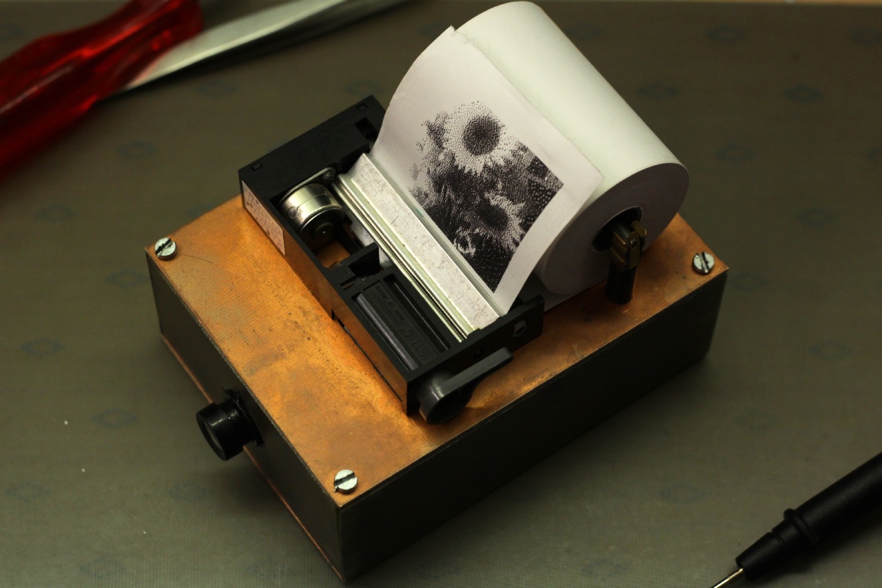
But, what do you do with a thermal printer? I remembered distantly having watched a video by mikeselectricstuff about interfacing cheap CMOS camera modules to microcontrollers. Thus, the plan: Some sort of a crude instant camera was to be built, from a OV7670 camera module, a LTP1245 thermal printer, and one of those ever-so-popular STM32F103C8T6.
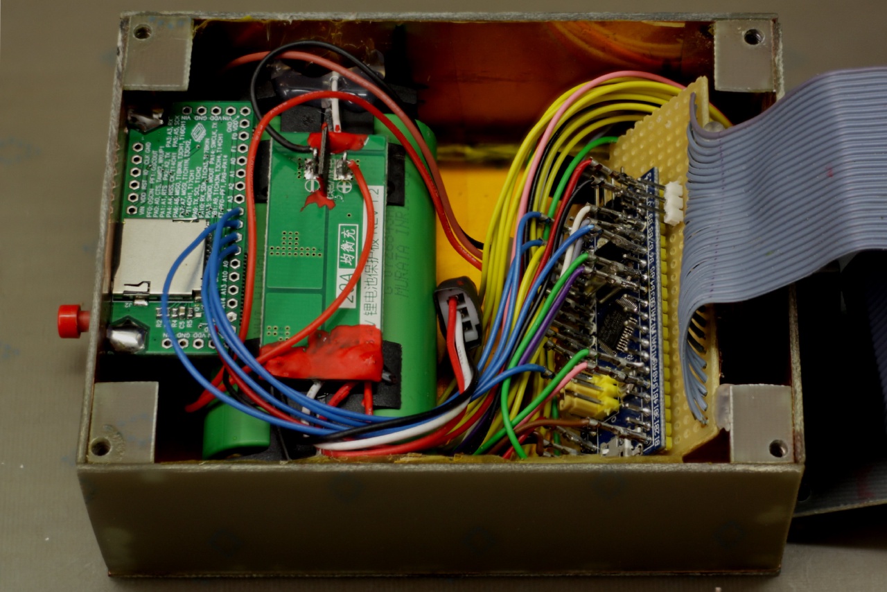
I chose this controller because I didn’t want to layout and etch a custom PCB and rather spend more time on the software for this weekend project. All development/evaluation boards with more powerful controllers I had were too large for the small, portable thermochromic selfie camera I had in mind. Thus, I started with a blue pill board to see how far I could get. It turned out to be trickier than anticipated, mainly for the following reasons:
- The STM32F103C8T6—of course—has no camera interface, but no memory controller either (which is used in the video linked above).
- 20 KiB RAM is really not all that much when dealing with image data.
- This might have been the first time when I ran out of timers on a STM32.
Output
I started with the printer module. Even though the LTP1245 does not need much external driver circuitry, it isn’t all that complex internally either. Apart from the paper feed mechanics with its stepper motor it contains:
- A shift register for the pixel data with an output latch.
- A power transistor for each pixel’s heater.
- Two photointerrupters to determine the print head position and the presence of paper.
- A thermistor to measure the print head temperature.
To print a line of pixels, the data has to be clocked into the shift register and the print head activated for a certain amount of time via the output latches. For the next line, the paper is advanced with the stepper motor and the process repeats. The time the latches are on is calculated from the supply voltage, the print head temperature (hence the thermistor), and some constants for the paper in use. This allows for a controlled energy to be dumped into the thermochromic coating and thus repeatable print quality.
The print speed is mostly limited by the stepper motor (and naturally goes up with rising supply voltage). To drive it, I used two emitter-follower pairs for each stepper phase. Since the motor isn’t all that high-power and current limiting or microstepping isn’t necessary, there is no need for a special driver or control IC and this solution is more than sufficient.
Software-wise, measuring the head temperature, feeding the paper, and printing line by line ends up as one straightforward state machine. In addition to line-wise black-and-white image printing I wrote a simple text renderer—it wasn’t used in the end but was nice to have for debugging. The printing software also generates a PWM signal for a servo to drive a paper cutter (which didn’t land in the final product either).
That covers the ‘output’ of the system, already! With the printing running, I could direct my efforts to the camera module.
Input
The OV7670 has a low-speed I²C bus for configuration and a high-speed parallel bus for the image data. The clock for the latter is generated directly by the camera sensor IC from a input clock. It can be configured pretty freely but as there is no buffer: it is always directly linked to the frame timing.
Because I had no camera or memory interface available and only limited RAM, I needed to reduce the image resolution and configure the pixel clock to be as slow as possible. Because the thermal printer only has 384 pixels per line anyway, this doesn’t really hurt. The camera IC’s documentation isn’t really clear on how the different settings interfere with each other, so figuring out the best configuration took quite a bit of trial and error. These are the settings I ended up using:
// Disable timing resets
WriteRegister(REG_COM6, 0x00);

// Set clock prescaler to 2
WriteRegister(REG_CLKRC, 0x4 | 1);

// Enable scaling
WriteRegister(REG_COM3, 0x08);

// Use QCIF output format
WriteRegister(REG_COM7, 0x08);

// Blank pixel clock during sync pulses
WriteRegister(REG_COM10, 0x20);

// Enable pixel clock scaling
WriteRegister(REG_COM14, 0x18 | 1);
WriteRegister(REG_SCALING_PCLK_DIV, 1);
With the camera now spitting out parallel data, the STM32 still needs to capture it somehow. This works as follows:
- VSYNC is wired to a timer input capture pin and triggers an interrupt for each pulse. This marks the beginning of a new frame and is thus used to reset a line counter or stop the whole data acquisition once a passable image has been acquired (we only need one after all).
- Similarly, HSYNC uses another timer input capture channel to generate an interrupt as well. For each interrupt call, the line counter is increased and the DMA is reconfigured.
- Last but not least, the pixel clock is connected to a third input capture channel. Since an interrupt for each pixel would be much too slow, the input capture issues a DMA request. The DMA has been configured in the previous HSYNC interrupt to read from the LSBs of port B, which are connected to the camera module’s data lines, and write to RAM, incrementing its RAM pointer afterwards. Thus, the DMA automatically transfers a whole line of pixel data to an arbitrary location.
The pixel clock can be configured to be blanked during synchronisation pulses. With clock edges only for valid pixels, no unnecessary data gets dumped into RAM and the scheme works out as planned.
Image processing
This leaves us with 160 times 144 pixels of image data. If you’re following along, you’ll notice that one frame already has 22.5 KiB and would be larger than the MCU’s entire SRAM. This also makes it obvious why I cannot omit the HSYNC interrupt and read an entire frame into memory.
Thankfully, the HSYNC blank is long enough to do some very basic image processing. Each line is dithered and converted to black and white right after it has been received. This reduces the memory footprint to an eighth and makes the whole endeavour manageable. The dithering used a very simple 1-D error diffusion method, which I later upgraded to full Floyd-Steinberg dithering. I kept the 1-D dithering as an option as I kind of liked its aesthetics.
Once a full frame is read and converted to black and white, the image capture can be stopped and the data sent off to the printer. After printing is done, the camera turns its own power off via a p-channel MOSFET, waiting for its next activation.
Room for improvement
At this point, I considered the project good enough. It has been fun and has been proven a fun party gimmick. However, there are still some issues with it:
- The slow pixel clock leads to severe rolling shutter effects. If the camera is moved around while taking a picture, it’s visible in spite of the low resolution and distorting image processing.
- The camera module I used has a rather narrow field of view. For a (single person) selfie, it has to be held at arm’s length. Since there’s now viewfinder it’s actually pretty hard to take photos of something or somebody else, too.
- The software does not itself compensate for under- or overexposure in any way. In fact, it assumes more or less correct exposure for the dithering to deliver a good-looking result. Because there is not enough RAM to keep a complete unprocessed frame in memory, exposure correction would only be possible across multiple frames. Currently, only the camera module’s auto-exposure stands in between varying light conditions and pure black or white pictures. Because the camera module only receives power when the user wants to take a picture, it has very little time to adjust to the lighting. After a few experiments waiting for a few frames was still the best solution I could come up with.
A bit less ephemeral (Update July 2020)
As the camera has been sitting around for a while (still seeing occasional use), I finally wanted to tack on one last feature onto the already pretty hacky camera. The issues listed as bullet points above are pretty much design limitations and thus hard to fix (without a general overhaul). It was time for something else: a more traditional image output format rather than just receipt paper.
I actually wanted the camera to have a SD card slot since the very beginning of the project. This however didn’t happen at first because whichever way I could look at it, there just wasn’t any SPI peripheral free: One was necessary for the thermal printer and the camera’s parallel port occupied quite a bite of I/O space.
However back then I didn’t realise that FatFs comes with a very easy-to-port bit-banging example. Saving a photo to SD storage after it is taken can be as slow as it wants to be, so the data transfer speed doesn’t matter at all. Using bit-banging SPI meant I wasn’t limited by the available peripherals and just had to make room for 4 GPIOs.
Four pins were enough since I skipped the card detect switch. If no SD card is plugged, mounting simply fails and the photo saving procedure aborts early. Because there is no additional user feedback there is actually no benefit to being able to detect the physical presence of an SD card.
I used one of the pins of the external 32 kHz crystal and freed others by removing unnecessary functionality like the paper cut servo and status LED. The on-board crystal can stay connected—it doesn’t disturb the digital signals noticeably.
To actually store useful files I wrote a very basic bitmap file output routine for the dithered image stored in RAM. Because it is a pretty low-resolution two-colour image which usually doesn’t have large uniform areas (due to the dithering), BMP is actually close to optimal and not just easy to write. A BMP won’t hold any metadata, but there wouldn’t really be any to store anyway.
The last piece to the puzzle is the file name to save the picture to. To obtain it, the firmware simply iterates through all TCIM-nnn.BMP (for thermal camera image, alluding to the typical folder DCIM) files, increasing the trailing number nnn until it finds one which doesn’t exist yet. This preserves the order in which photos are taken (unless some are deleted manually) without the need for an additional counter stored somewhere in flash, at the expense of a potentially slow saving process. Because, as previously mentioned, it doesn’t matter how long the camera keeps processing after it’s done printing, this isn’t a problem.
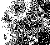
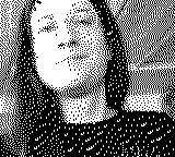
The digital copies of the printed photos naturally look nowhere near the same, being presented on completely different media. However, as they are still the same low-resolution, low-fidelity images, I think they retain quite a bit of their appeal. All in all, having the option of a digital copy with at least part of the aesthetics of the prints is a strict improvement because the camera can still be used in its original form—leaving behind no record apart from the quite volatile receipt paper.
Links
The source code is available here.